Cutting and ripping materials for making custom wooden parts

Creating unique, custom wooden parts — this is what sets true craftsmanship apart from assembly-line production. In woodworking, where every material has its own texture, grain direction and unique characteristics, the process of cutting and ripping becomes not just a technical operation but a critically important stage that determines the quality, durability and aesthetics of the finished product. Complex, curved or oversized parts, where standard blanks do not fit, call for a special approach to planning and executing these initial operations. Here it is not speed that comes first, but precision, waste minimisation and a deep understanding of the properties of wood.
Preliminary drawing analysis and material selection
🧐 Understanding geometric complexity
The first and most crucial step is a detailed analysis of the supplied drawing or specification. If a part is custom, this almost always means it has complex radii, non-parallel edges, unusual angles or a combination of thicknesses. You need to determine precisely which sections of the part will bear the greatest load, where maximum strength is required and where flawless surface texture matters. This analysis dictates not only the sequence of sawing but also a key choice: which material — solid wood, glued panel or sheet material (plywood, MDF) — the part will be made from, and how best to orient it relative to the material’s structure.
🌲 Accounting for grain direction in solid wood
When working with solid wood, making custom parts is inextricably linked to grain direction. For curved elements such as chair curves or decorative overlays, the correct orientation of the grain relative to the cutting line is critically important. If the cut runs across the grain at a bend, it weakens the part and makes it prone to cracks or chips during machining. An experienced production engineer always aims to place the long, load-bearing parts of a piece along the grain, even if this requires a wider or longer blank, thereby sacrificing economy in favour of strength and stability.
🔍 Assessing blank quality and defects
Before ripping begins, every blank must be inspected carefully. In solid wood this means identifying knots, cracks, resin pockets, areas of discolouration or developmental defects . For custom parts, which often use large areas of material, it is critically important to mark out the part so that the cutting lines bypass the largest or structurally weakening defects. This is especially relevant for visible surfaces, where defects may be unacceptable under the specification. When working with glued material (panel), the quality of the bond and the uniformity of the lamellae are assessed.
🪵 Choosing the optimal thickness and allowance
Custom parts often require non-standard thicknesses. The choice of starting material thickness must account not only for the final dimension but also for a sufficient allowance for subsequent machining: jointing, thicknessing, sanding, as well as compensation for the deformations that can arise after internal stresses are released during initial ripping. Skimping on thickness can result in the part not reaching its final size or developing surface defects.
📊 Comparative analysis of sheet materials
When it comes to sheet materials (for example, moisture-resistant plywood for radiused elements or thick MDF for milling complex relief), analysing the drawing includes assessing the material’s density, coating wear resistance and stability . Plywood makes it possible to create curved parts through layered gluing, whereas MDF is ideal for deep profiled milling, where uniformity of structure matters. The choice of material directly affects the required ripping precision and the type of tooling used.
📉 Planning to minimise waste
Although quality and strength take priority when making custom parts, cutting planning always includes the task of minimising waste. For expensive or rare timber species, a cutting map (custom nesting)is developed that takes into account dimensions, grain orientation and the location of defects to maximise the yield of good parts. This is an iterative process, often carried out using specialised software that helps optimally position many parts on a single board or sheet.
🌡️ Accounting for moisture and storage conditions
It is important to ensure that the material used has an optimal moisture contentmatching the service conditions of the future part. Cutting and ripping wood with excessive moisture will lead to significant changes in dimensions and shape (shrinkage, warping) after machining. Custom parts requiring high precision must be made from stable, acclimatised material.
📝 Recording the initial parameters
Before cutting begins, all the initial data must be recorded: final dimensions, tolerances, type of material, its moisture content and the location of defects. This serves as the basis for quality control at subsequent stages and makes it possible to trace potential problems back to the original blank.
🧩 Developing the cutting process map (nesting)
🗺️ Fundamentals of custom nesting
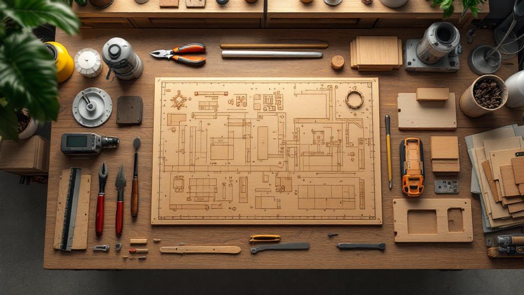
The cutting process map, or nesting, is a plan for laying out the contours of future parts on the starting blank. For standard rectangular parts this process is simple and often automated. However, for custom parts (complex curves, cut-outs, varying thicknesses) manual or semi-automatic optimisation is required. The goal is not only to minimise waste but also to ensure the correct grain orientation for each part, as well as to keep defects out of critical zones.
🖥️ Using specialised software
To nest non-standard shapes efficiently, specialised CAD/CAM softwareis used. It lets you enter the contours of the parts and the dimensions of the source sheet or board, and then suggests optimal layout options. The software takes into account the kerf width (tool gap), the grain direction, and can also define exclusion zones (defect locations). Using software significantly reduces the percentage of waste, which is critically important when working with expensive timber species.
📐 The “largest to smallest” principle
In manual or semi-automatic cutting planning, the “largest to smallest”principle is used. First, the largest and most complex parts, which require a specific grain orientation, are laid out on the blank. The remaining gaps (offcuts) are used to place smaller parts that are less demanding of grain direction. This makes it possible to use the material area to the maximum.
✂️ Accounting for kerf width
Kerf width is the amount of material turned into sawdust during cutting. For high-precision cutting, especially on multi-blade or panel saws, it is necessary to account for the fact that this width, usually 3 to 5 mm, must be added to the calculated dimensions. In the case of custom parts, where the cut may be curved or angled, correctly accounting for the kerf prevents dimensional errors and allows the gap between adjacent parts on the sheet to be designed precisely.
📈 Creating allowances for curved cutting
For parts that will be further machined on a band saw or CNC router, it is necessary to provide process allowances. This is an extra margin of material along the contour that will be removed at the next stage. For example, for subsequent finish milling to a template, the blank can be ripped with a 2–5 mm allowance so that the tool can remove all traces of rough sawing and produce a perfect contour.
🔄 Planning the ripping sequence
The process map must include not only the layout but also the cutting sequence. An incorrect sequence can cause already-cut pieces to become unstable, vibrate or shift, leading to inaccuracy in the final cut or even injury. Typically, longitudinal cuts are made first, trimming the edges and squaring the reference sides, then cross-cuts, and only after this does curved or angled ripping begin.
📍 Defining reference surfaces and marks
A key point in cutting is defining the reference surfaces (datums). These are the surfaces from which all other dimensions and angles will be measured. For a custom part, the datum may be the straightest edge or end. The cutting drawing must always indicate the process marks and reference points that will be used to position the blank on the machine or for manual marking.
🛡️ Accounting for possible damage
When planning the nesting, it should be ensured that complex, thin or long parts do not end up right at the end of the cut, when they can easily vibrate or break off. Correctly positioning the parts on the sheet is also about preventing mechanical damage to already-finished pieces during the final cut.
Tools and equipment for ripping solid wood
⚙️ Choosing the main cutting equipment
Several types of machine are used for the initial ripping of solid wood. Panel saws are ideal for high-precision straight cuts with a clean edge, which matters for subsequent gluing or finish machining. Mitre saws are used for precise cross-cutting and trimming out defects. However, for custom parts, especially those with curved contours, the band saw.
🪚 The band saw — king of curved ripping
The band saw is the main tool for rough cutting of curved contours. Its advantage lies in the narrow blade, which allows radius cuts to be made with minimal resistance. To achieve a quality cut, the blade’s width and tooth pitch must be selected correctly. A wider blade gives a straighter cut but limits the minimum radius, whereas a narrow blade allows steep curves but requires more care during feeding to avoid blade drift.
🔺 Multi-blade machines for volume and precision
If it is necessary to make a large number of identical narrow parts that are non-standard in length (for example, elements of curved fronts or complex-profile mouldings), multi-blade machines may be used after preliminary cutting. These machines, fitted with several circular blades, provide high productivity and accuracy of parallel cuts. However, they require very precise preliminary setup and a stable blank.
💻 Using CNC routers for high precision
For the most complex, high-precision or repetitive custom parts, ripping can be carried out directly on a CNC router. A CNC router is able not only to cut a complex contour but also to simultaneously produce chamfers, grooves and holes. In this case, ripping and rough machining are combined into a single operation, ensuring the highest precision of contour with a minimal allowance for finish machining.
🛡️ Selecting and sharpening the cutting tool
The quality of ripping depends directly on the condition of the cutting tool. For a clean cut in solid wood (especially end-grain or angled cuts), circular blades with the optimal number of teeth and an appropriate sharpening angle are required. A blunt or incorrectly sharpened tool causes chipping, grain tear-out, overheating and increased material wear. Regular professional sharpening is not just maintenance; it is part of the technology of high-precision cutting.
💨 An effective dust extraction system
Ripping material generates a large amount of wood dust and sawdust. Effective dust extraction does not just keep the workplace clean but directly affects cut quality. A build-up of sawdust in the cutting zone can cause the saw to overheat, obscure the marking-out and, as a result, reduce accuracy.
🛠️ Auxiliary jigs and fixtures
To ensure safety and repeatability when ripping custom parts, special jigs and fixturesare used. These may be sleds for cross-cutting at non-standard angles, fences for the band saw, or hold-down clamps that keep the blank in a stable position during the cut. Such devices are critically important in serial production, even of small custom batches.
📏 Measuring and inspection instruments
An indispensable element of the process is the use of precise measuring instruments (callipers, protractors, laser levels). Even the most modern equipment requires checking. Periodic measurement of ripped parts makes it possible to promptly correct the machine settings and prevent defects.
Cutting and ripping of sheet materials
🧱 The role of sheet-material uniformity
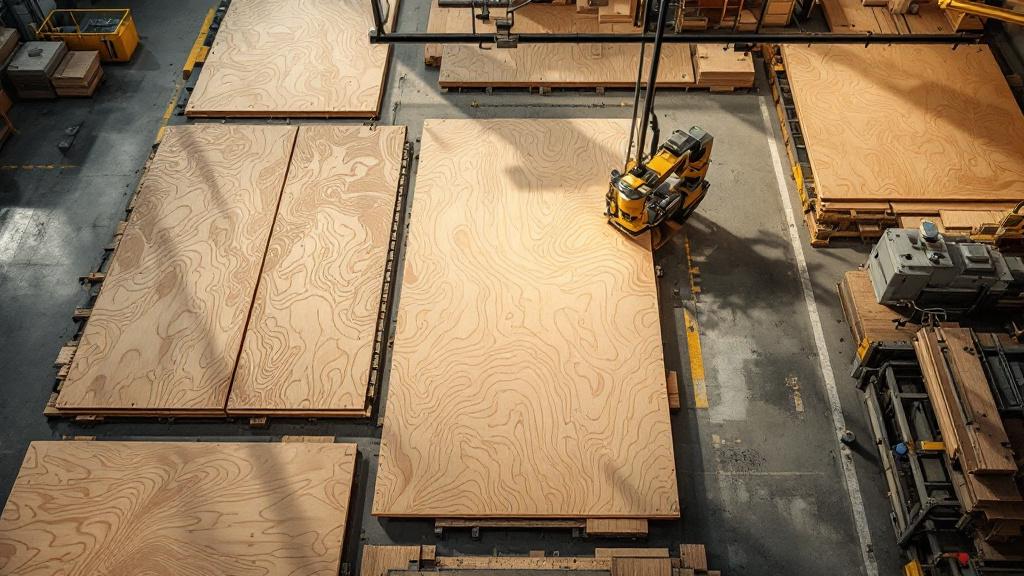
Sheet materials such as MDF, particleboard or plywoodhave considerably greater uniformity compared with solid wood, which simplifies cutting calculations, since there is no need to account for grain direction or internal defects. However, cutting them has its own peculiarities related to the multilayer structure and the presence of facing coatings (laminate, veneer).
🔪 The problem of chipping on faced boards
The main problem when cutting sheet materials, especially laminated (MFC) or veneered ones, is chipping of the top layer. To prevent chipping, panel saws with a scoring bladeare used. The scoring blade, mounted ahead of the main one and rotating in the opposite direction, makes a shallow but clean cut that prevents the main blade from tearing off the fibres or laminate.
💧 The effect of moisture on MDF and particleboard
Although sheet materials are more stable than solid wood, MDF and particleboard are sensitive to moisture. Cutting in high-humidity conditions can cause swelling at the edges, which then complicates edge-banding or milling. Storing material in dry conditions and using a clean, sharp tool minimise this risk.
🌀 Curved cutting of plywood and MDF
To create curved custom parts from sheet materials, it is best to use a CNC router. Unlike a band saw, which leaves a blade mark, milling produces a perfectly clean edge and high contour accuracy that often requires no subsequent mechanical rework. For thicker sheets of plywood and MDF, milling is done in several passes (in terms of depth) to avoid overheating the tool and destroying the material’s structure.
📈 Cutting thin veneer
When it comes to making parts faced with thin veneer, cutting must take the fragility of this layer into account. Often the substrate (MDF, particleboard) is ripped first, and then the already-glued veneer is trimmed using precision tooling (veneer guillotine shears or fine cutters) to prevent it from cracking and chipping.
🌬️ Combating dust when cutting MDF
Cutting MDF generates very fine, harmful dust. An effective, high-power dust extraction system with good filtration is a mandatory requirement. In addition, the tool for MDF must be fitted with carbide tips to withstand the abrasive nature of the material.
📏 Precision for hardware grooves
Custom parts made from sheet materials often require high precision, because they must mate with complex hardware (for example, concealed fasteners or transformation mechanisms). Cutting accuracy is important here for the subsequent precise positioning of hardware grooves and holes, which are often milled after cutting. Any deviation in the geometry of the blank will cause the fastening points to shift.
📝 Marking and identifying parts
When cutting a sheet into many custom parts in bulk, a labelling systemis extremely important. Each part must be clearly identified (number, name, side) to avoid confusion at the assembly stage. Labelling printers integrated with the cutting equipment are often used for this.
📏 Process allowances and tolerances for non-standard shapes
🎯 The need for allowances for finish machining
For custom parts, especially those with curved contours or that will undergo complex milling, process allowances are mandatory. An allowance is an extra layer of material left during rough ripping that will be removed at the finish-machining stage (template milling, sanding). This margin compensates for the inaccuracies of the rough cut (imprecision of the band saw), makes it possible to remove saw marks and, most importantly, ensures the removal of the surface layer that may have been damaged or stressed during initial ripping.
✂️ Calculating the allowance value
The allowance value depends on several factors: the type of material, the accuracy of the rough equipment and the surface-finish requirements.
- For ripping on a band saw before finish milling, the allowance may be 2 to 5 mm.
- For ripping on a CNC router (if it is a rough pass) the allowance may be minimal, around 0.5 to 1 mm, for a subsequent finish pass with the same router.
- For parts requiring gluing (for example, laid-up elements), the edge allowance can be up to 1 mm to ensure a flat, clean surface for adhesion.
⚖️ Tolerances for shape and dimension
Tolerances are the permissible deviation from a specified dimension or shape. For custom parts that must mate precisely, manufacturing tolerances can be very tight, for example +/- 0.1 mm. When planning the cutting, the production engineer must ensure that even at the maximum permissible deviation (within tolerance), the part will not exceed limits that could affect its functionality or appearance.
🌡️ Compensating for shrinkage and warping
When ripping solid wood, especially over long lengths, internal stressesmay appear, leading to warping or a change in the geometry of the blank. A properly planned allowance takes this possible change into account. After rough ripping, a process pause is sometimes made to allow the stabilisation of the material before finish machining.
🔄 Allowances for angled and mitre cuts
Custom parts often have complex angled or mitre cuts. In this case the allowance should be increased, because the accuracy of angled sawing, especially on mitre saws, can be lower, and also to provide enough material for precise alignment during gluing. The allowance on an angled end can be larger than on a longitudinal edge.
📏 Calibration after ripping
For critical parts requiring precise mating, an intermediate operation may be needed after ripping — calibration. This may be a pass through a thicknesser to achieve the perfect thickness or a pass through a jointer to create a perfectly flat reference edge. Allowances are also calculated for this operation.
📝 Accounting for tolerances in software
When using a CNC router for cutting, the parameters of allowances and tolerances for finish machining are entered directly into the CAM program. The operator must clearly define the roughing and finishing passes, specifying how much material is to be left after the rough cut.
🧩 Allowances for gluing into complex shapes
If a custom part is formed from several pieces glued at an angle (for example, polygonal columns or radiused panels), the allowance on the glued edges should be minimal (for a clean joint) but sufficient to create a flat, perpendicular surface.
🌲 Ripping of valuable and exotic species
💎 The value and high cost of the material
Working with valuable and exotic timber species (wenge, macassar, zebrawood, American walnut) places the highest demands on the cutting process. The main task is to maximise the yield of good parts and minimise waste. Every cut must be carefully planned to eliminate rejects. Mistakes here are very costly.
🔪 Brittleness and hardness
Many exotic species are notable for their increased hardness and, at the same time, their brittleness or oiliness. Hardness requires the use of a tool with high-quality carbide tips and a reduced feed rate. Brittleness, characteristic of wenge for example, increases the risk of chipping and tear-out of the fibres, especially during end-grain cutting or angled ripping.
🌈 Considering and preserving the texture
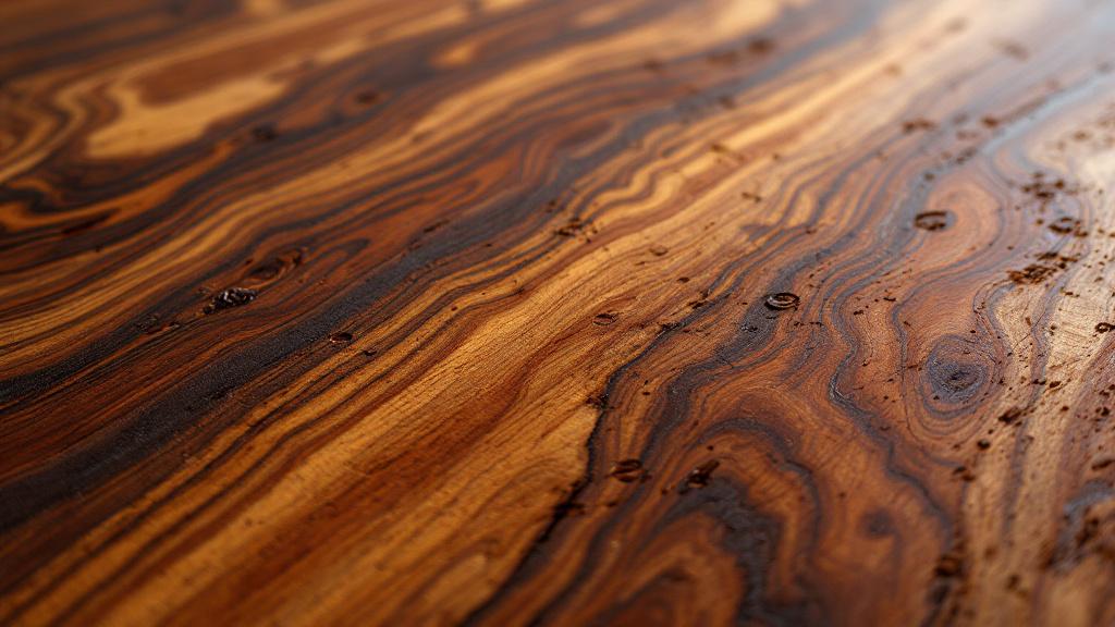
For valuable species such as zebrawood or American walnut, the texture (figure) is the principal aesthetic value. When cutting a custom part, it is necessary to consider how the cutting lines will affect the final figure. The production engineer must position the part’s contour so that the unique figure is as expressive as possible on the face side. Sometimes this requires positioning the part in a way that is not optimal in terms of waste.
🌡️ Temperature regime and resin content
Some exotic species, for example teak, have a high resin content. During cutting the resin can stick to the saw blades, worsening cut quality, causing overheating and reducing accuracy. It is necessary to use special resin removers and to clean the tool regularly.
💨 The impact of toxic dust
Dust from some exotic species (for example, ipe, jarrah) can be toxic or cause allergic reactions. When ripping these materials it is extremely important to use highly efficient dust extraction systems and personal protective equipment (respirators).
📝 Creating a detailed defect map
For expensive slabs or wide boards, thorough mapping of all defects, imperfections and colour transitionsis carried out before ripping. Marks are applied to the blank to help exclude unwanted areas from the part’s contour. Sometimes a small but visually significant defect can be used as a decorative element if agreed with the customer.
🔄 Planning a set of several boards (bookmatching)
For wide custom parts glued up from several narrow boards, the “bookmatching”technique is often used. When ripping a slab, adjacent lamellae are ripped and glued so that the texture at the joint forms a symmetrical, “open” figure. This requires very precise longitudinal ripping with a minimal edge allowance.
🛠️ Using hand operations
For the most careful cutting of the most valuable and delicate areas, the use of hand tools or precise chisels and saws may be justified to avoid the vibration and chipping that mechanical sawing can cause.
🌀 Ripping material for bent-laminated parts
➰ Fundamentals of bent-lamination technology
For creating radiused (bent-laminated) custom parts (for example, fronts, handrails, furniture elements), ripping the material takes on specific features. The part is formed not from a single solid piece but from many thin lamellae (strips)that are glued together in a special form (jig) under pressure, following the required radius.
📏 Ripping into lamellae (thick ripping)
The main task here is the longitudinal ripping of the source board into lamellae of the required thickness.
- The lamella thickness is chosen based on the bend radius and the timber species. The smaller the radius, the thinner the lamella must be.
- A high level of precision in the longitudinal ripping (parallelism and uniform thickness) is required to ensure even contact and a tight glue joint.
🌲 Accounting for grain direction in lamellae
Unlike an ordinary part where the grain runs lengthwise, when ripping into lamellae it is important for the grain to be strictly parallel to the plane of the cut. This prevents the lamella from splitting during its subsequent bending in the form. The source board should be of radial or semi-radial cut.
🔪 Tooling for a clean longitudinal cut
For ripping lamellae, a multi-blade or circular saw with a very thin and sharp saw bladeis used. It is important that the cut be as clean as possible, since the lamella edges will become glue surfaces. A dirty or rough cut will worsen the quality of the glue joint.
⏳ Lamella length and gluing allowances
The lamellae must have a sufficient length marginto compensate for their shortening during bending, as well as an allowance for subsequent trimming and cutting to contour after gluing. This allowance can be 5–10 cm.
🛠️ Splicing lamellae to length
If a very long bent-laminated part is required (for example, for a long bar counter), the lamellae can be spliced to length using a “scarf” joint (mitre) or a “mini finger joint”. The ripping must provide precise angles for these joints.
📈 Cutting plywood for forms
The form itself, in which the gluing takes place, is often made from thick plywood or MDF. Cutting these materials to make the forms must be done with the highest precision (often on CNC), because any inaccuracy in the form will be reflected in the final geometry of the bent-laminated part.
📝 Number of lamellae and pack thickness
The production engineer must accurately calculate the required number of lamellae to obtain the required final thickness of the bent-laminated part. The thickness of the glue layer, which adds 0.1–0.2 mm per joint, is taken into account.
📐 Precision and calibration during ripping
🎯 Monitoring perpendicularity and parallelism
To ensure high quality of custom parts, ripping precision is of paramount importance. The main monitored parameters are: perpendicularity (a right angle between face and edge) and parallelism (uniform width along the whole length). A deviation of these parameters at the ripping stage cannot be fully compensated for in subsequent operations.
🔬 Using precision instruments
For inspection, high-precision measuring instruments:
- are used. Digital protractors to check the tilt of the saw blade.
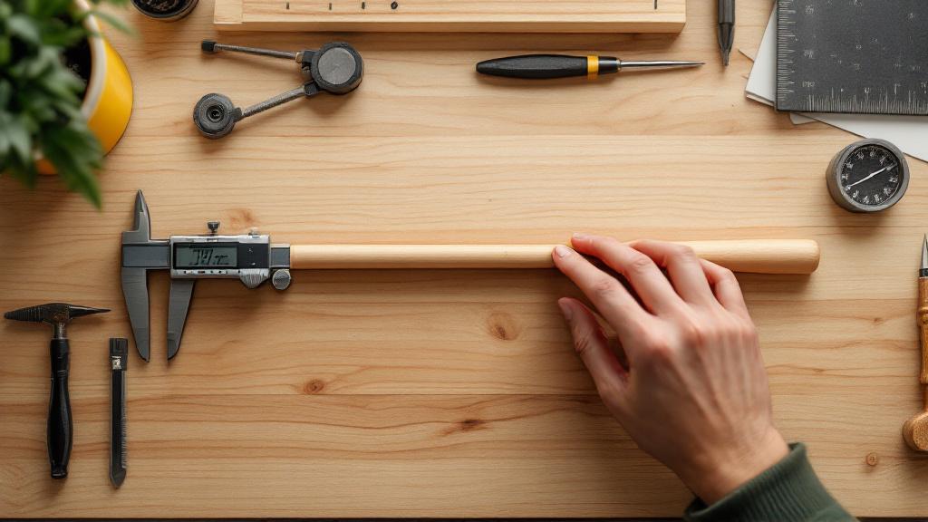
- Callipers and micrometers to measure thickness and width to within 0.05 mm.
- Laser levels and rulers to check the flatness of tables and guides.
🛠️ Machine calibration procedures
Regular calibration and setup of the cutting equipment is a mandatory process procedure. This includes:
- Levelling the tables and guides.
- Checking the alignment of the scoring and main blades.
- Adjusting the position of stops and fences.
📉 The “datum” principle
All measurements and subsequent operations (jointing, milling) must be based on one and the same reference surface. If an uneven or non-perpendicular edge is created during ripping, it cannot be used as a datum. That is why the first cut is always the creation of a perfectly flat and perpendicular edge.
🔄 Intermediate inspection and correction
For long or wide custom parts, dimensions are monitored continuously or after ripping every fifth or tenth blank. If a deviation is found, the operator immediately stops the process, corrects the machine settings and checks the tool.
📝 Accounting for tool wear
As work progresses, the cutting tool wears down. A blunt saw leads to increased feed force and overheating, and may also cause slight cut drift, which reduces accuracy. The process must set a working-time limit for each tool before its mandatory sharpening.
🌬️ Temperature stabilisation
In workshops that require high precision, temperature and humidity are monitored. Significant fluctuations can cause a slight but critical change in the dimensions of both the blank itself and the metal parts of the machine, which matters for high-precision parts.
💻 Software correction
In CNC equipment, software correction (tool offset) is possible, which makes it possible to compensate for a minimal deviation of the cutting tool from the ideal path, ensuring maximum contour accuracy.
🚫 Preventing ripping defects
💥 The problem of tear-out
Tear-out is the tearing away of wood fibres or the top layer of sheet material as the saw blade exits. For custom parts, where edge cleanliness is critical, this is unacceptable. Prevention:
- Using a scoring blade on sheet materials.
- Using anti-chip inserts on circular and panel saws.
- Using a very sharp tool with the correct tooth geometry.
- Ensuring slow and even feeding of the material.
🌳 Blade drift
Blade drift is the deviation of the cut line from the intended path, often encountered on band saws. Causes: incorrect blade tension, a blunt or incorrectly set tooth. Drift leads to non-parallel edges and material loss. Solution:
- Regular tension checking of the blade.
- Using a blade with the correct tooth set .
- Ensuring smooth and controlled feeding of the material without excessive pressure.
♨️ Burning
Burning is the blackening of the wood in the cutting zone due to overheating. It happens because of a blunt tool, too slow a feed or resin build-up. Burning not only spoils the appearance but also hardens the surface, which complicates subsequent machining (sanding).
📐 Non-perpendicularity and taper
If the saw blade is not set strictly at 90 degrees to the table, this leads to non-perpendicularity of the edge (an angled cut). If the guide fence is not parallel to the saw blade, this leads to taper (different widths at the start and end of the part). These defects critically affect the mating of parts. Solution:
- Regular calibration of angles and fences.
- Using precision protractors.
🛠️ Combating vibration
Vibration of the machine or the blank can lead to waves on the cut surface and reduced accuracy. The cause may be an unbalanced tool or insufficient clamping. For custom parts, especially narrow or long ones, it is necessary to use additional clamps and supports.
💧 The effect of material moisture
Cutting material with uneven or excessive moisture can cause warping of the parts immediately after cutting, when internal stresses are released. Always use material acclimatised to the workshop conditions.
📝 Documenting defects
When a recurring defect is discovered, it is necessary to immediately document it, determine the cause (material, tool, operator, machine) and take measures to eliminate it.
💡 Ripping and cutting for subsequent CNC machining
💻 Integrating cutting with the CNC program
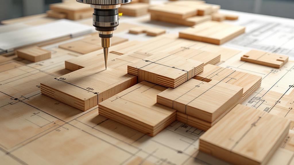
For complex custom parts that will be machined on CNC routing centres, the ripping process must be integrated as closely as possible with the subsequent milling program. The goal is to provide a blank that precisely meets the program’s requirements for dimensions and allowances.
📏 Allowances for CNC
Earlier, during rough cutting on the band saw, a large allowance was left. When preparing a blank for CNC machining, it is often enough to leave a minimal allowance (1–2 mm) along the contour. This allowance will be removed by a finish pass of the router. Precision in ripping here makes it possible to save time on CNC machining.
🔗 Defining the zero point
During ripping, a reference surface (datum) or a reference pointmust be created, which will then be used as the zero point for the CNC program. For example, a perfectly flat and perpendicular edge or corner from which all coordinates will be measured. An incorrect datum will cause the entire milling path to shift.
📌 Ripping for nesting on CNC
Sometimes, to minimise waste, so-called “nesting”is used, where many small parts are cut from a single large sheet on the CNC machine itself. In this case, ripping the sheet comes down to sizing it to fit the CNC work table.
🪚 Using tabs
During CNC cutting , the parts are not cut out completely but remain attached to the main sheet of material by “tabs” (small bridges). This prevents the part from shifting or vibrating during the final cut. At the ripping stage the sheet of material must be perfectly flat to ensure a secure attachment to the CNC table.
📝 Identification and orientation
Since the CNC program works in a strict coordinate system, it is extremely important for the CNC operator to know exactly how the blank was oriented during ripping, so that the grain direction matches and errors in the placement of parts are avoided.
Conclusion
Cutting and ripping is not merely a preparatory stage but a cornerstone in the production of custom wooden parts. The quality, precision and thoughtfulness of this process directly determine not only the economics of production (waste minimisation) but also the final quality, strength and aesthetics of the product. Working with non-standard shapes requires a deep understanding of materials, mastery in handling precision equipment and strict adherence to the process map, which is a sign of high professionalism and a guarantee of the durability of wooden products.
Key aspects of successful ripping of custom parts:
- Thorough drawing analysis: Identifying critical zones and the required grain orientation.
- Optimal planning: Using nesting to maximise material yield while accounting for defects.
- Using precise equipment: Employing band saws, CNC routers and panel saws with a scoring blade.
Important process requirements:
- Allowances: A mandatory material margin for subsequent finish machining and to compensate for stresses.
- Precision: Strict control of perpendicularity, parallelism and the absence of chipping.
Mastering these subtleties allows us to turn raw material into unique, reliable and beautiful custom wooden products.